Who does what
Two parts of this install are not general-public work. One is the refrigerant circuit. The other is line voltage. Everything else is well within reach of a careful homeowner, and the guide is written so you can do that part yourself and hand over the rest.
- Mounting the unit on the condenser
- Fitting the antenna
- Taping on both temperature probes
- Plugging in the splitter harness
- Routing and tidying the cables
- Powering up, reading the lights, commissioning in the app
- Fitting the two service-port tees
- Fitting and leak-checking the pressure sensors
- Anything inside the electrical panel
- Landing the power supply on the contactor
Why those two are gated
Fitting a tee means opening a sealed refrigerant circuit. In the United States, EPA Section 608 certification is required to service, maintain or repair an appliance containing refrigerant, and knowingly venting refrigerant is illegal regardless of who you are or whose equipment it is. In Texas, doing that work for someone else for compensation also requires a TDLR air-conditioning and refrigeration licence.
The power supply lands on a contactor that sees roughly 240 volts. A condenser disconnect is not a wall switch, and the terminals stay live until you prove otherwise with a meter.
Neither of these is a comment on your ability. They are the two steps where being wrong costs a compressor, a citation, or a trip to hospital.
The split install
The practical route for most homeowners: do steps 1–4, 8, 10 and 11 yourself, then have your regular HVAC company fit the tees, sensors and power supply at your next service visit. It is about twenty minutes of their time on a system they already know, and you finish the commissioning yourself afterwards.
Does your system qualify
The monitor reads the refrigerant circuit directly, so the test is simple: is there a reachable direct-expansion circuit with service ports on both lines? If yes, it fits. Split systems, heat pumps, packaged rooftop units, mini-splits with accessible ports and most commercial refrigeration all qualify.
Good to go
- Schrader service ports you can reach on both the liquid and the suction line
- R-410A, R-22, R-454B, R-134a and similar — the sensors read 0–40 bar (0–580 psi)
- Line-voltage power at the condenser
- A mobile signal at the condenser — any carrier, the SIM is built in
- Packaged rooftop units. The question is the refrigerant circuit, never the cabinet shape
Stop and reschedule
- No service ports, or ports that are buried, seized or non-standard
- Chilled-water or water-source systems with no DX circuit to tap
- A system that is already failing — repair it first, then monitor it
- No power source within reach of the 2 m supply lead
- A condenser in a pit or a metal enclosure with no signal
A bad install is worse than no install. If something on the right-hand list is true, stop. Nothing about this product is improved by forcing it onto equipment that cannot carry it.
What's in the box

Already built into the unit
- The monitor, sealed, with a 25 mm magnet bonded into the base
- Three status windows on the front face
- A serial and QR label on the side
Loose in the box
- 1 antenna
- 1 splitter harness — one plug in, five labelled branches out
- 2 pressure sensors — one marked Liquid side, one Vapor side
- 2 brass tees — one per service port
- 2 temperature probes — one Liquid side, one Vapor side
- 1 power supply, 100–240 VAC in, 5 VDC out
- 4 insulation patches — two per temperature probe
- 10 zip ties
Lay all of it out on the pad before you start and check it against this list. The one thing you cannot improvise on a roof is a missing sensor.
Tools you need
For the homeowner steps
- Nut driver or screwdriver for the disconnect cover
- A non-contact voltage tester
- Small adjustable wrench
- Scissors or snips, and a rag
- Your phone, for the app and the photos
Additional, for the technician steps
- Gauges, recovery equipment, and nitrogen if a joint has to be opened
- Two wrenches — one to hold, one to turn
- Torque wrench, with the flare-fitting spec to hand
- Electronic leak detector or bubble solution
- Valve-core tool
- Multimeter
The unit itself
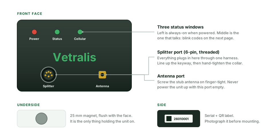
Three windows across the top. The left one is simply power — it lights the moment the unit has 5 volts and stays on. The right one follows the cellular modem. The middle one is the one worth learning: it is driven by the firmware and it tells you, in blink codes, exactly what state the unit is in. Step 12 has the full chart.
Everything except the antenna goes through the single threaded splitter port. There is no SIM to fit, no Wi-Fi to join and no configuration to enter — the cellular connection is built in and already paid for.
Where everything goes
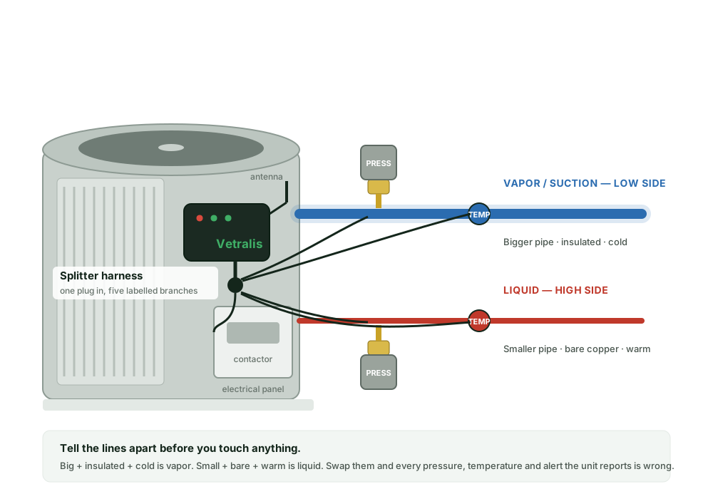
Telling the two lines apart
This is the one identification everything else depends on. Get it backwards and every pressure, every temperature and every alert the unit produces will be wrong — and it will look plausible, which is worse.
| Vapor / suction line | Liquid line | |
|---|---|---|
| Which side | The low side | The high side |
| Size | The larger of the two pipes | The smaller |
| Covering | Black foam insulation | Bare copper |
| Feel, while cooling | Cold, often sweating | Warm to hot — do not grab it |
| Gets | Vapor pressure sensor + vapor probe | Liquid pressure sensor + liquid probe |
On a heat pump in heating mode the temperatures swap over. The line identity does not: the large insulated pipe is still the suction line and still takes the vapor sensor. Identify by pipe size and insulation, never by which one feels cold today.
The fourteen steps
Kill the power and prove it dead
EveryonePull the disconnect beside the condenser. If the property has a breaker for the condenser, switch that off too. Then check with a tester at the disconnect terminals before your hands go anywhere near them.
Do not skip the meter. A pulled disconnect that turns out to be wired backwards is exactly the surprise this step exists to catch.
Identify the lines, and mark them
EveryoneFind both service ports. Confirm which line is which using the table above — bigger and insulated is vapor, smaller and bare is liquid. Then put a piece of tape on each and write on it. Ten seconds now, and you cannot mix them up later with cold hands and a dark yard.
While you are there, photograph the equipment nameplate. Make, model, serial and refrigerant type all go into the app at the end.
Mount the unit
Homeowner OKThe magnet in the base does the whole job — nothing to drill, nothing to screw. Pick a flat steel panel on the condenser cabinet, wipe it clean and dry, and set the unit down squarely. It holds through wind, rain and mowing, and it comes off with a firm pull when the equipment is next serviced.
- Level, and square to the cabinet edge. A crooked unit is the first thing anyone notices.
- Beside the manufacturer's labels, never over them. Covering a data plate creates a warranty argument you do not want to have.
- Not on the fan deck, and not where it blocks the coil face.
- Somewhere you can still read the three windows standing up.
Wipe the panel first. Dust and pollen under a magnet is the difference between holding for ten years and sliding down the cabinet in August.
Fit the antenna
Homeowner OKScrew the antenna onto the gold connector, finger-tight only — no wrench. Point it upward and keep it clear of the cabinet sheet metal. Never power the unit up with this port empty.
Fit the two tees
Licensed only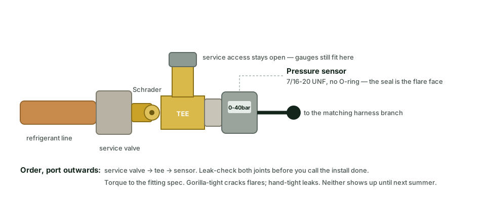
Remove the service port cap. The tee threads onto the port, the sensor goes on the branch, and the through-path stays available so gauges still fit for normal service. One tee per line, per the marking you made in step 2.
- Hold the valve body with a second wrench. Never let torque reach the line.
- Torque to the flare-fitting specification. Over-tight cracks a flare; hand-tight weeps. Neither shows up until next summer.
- Clean flare faces and clean threads. No tape and no sealant on a flare joint.
Fit the pressure sensors — the right one on the right line
Licensed onlyBoth sensors are the same part and both are marked. Liquid side goes on the small bare line. Vapor side goes on the large insulated line. The seal is the flare face, so there is no O-ring to fit and nothing to dope.
The one mistake that hides
A swapped pair does not fail. It reports. Every superheat and subcooling figure comes out inverted, the unit looks healthy while the system starves, and nothing in the data announces the error. Read both labels out loud against both pipes before you tighten anything.
Leak-check every joint you made
Licensed onlyTwo tees, two sensors, four joints. Check all four with a detector or bubbles, and document it. This step decides whether the charge is still there in two years, and it is the one nobody can verify for you afterwards.
Tape on the temperature probes
Homeowner OK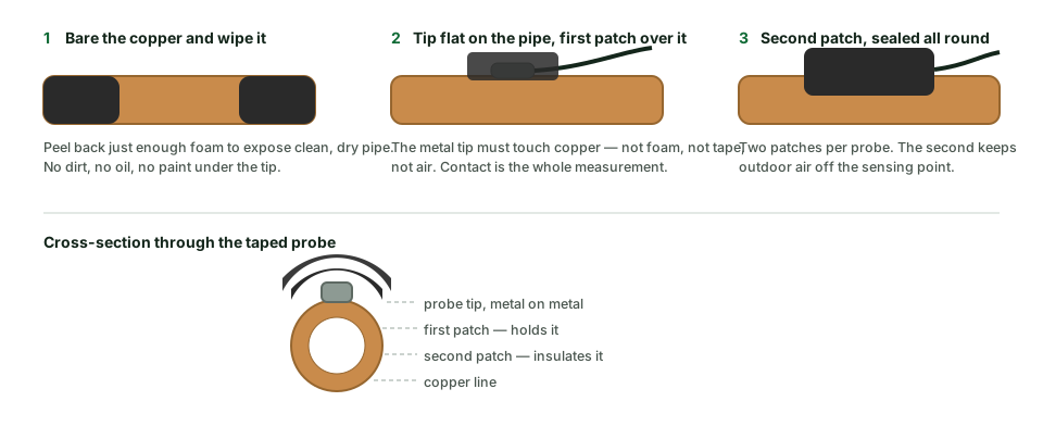
Each probe is marked for its line. Peel back just enough insulation to expose clean, dry copper about a foot downstream of the service port, lay the metal tip flat against the pipe, and hold it there with the first insulation patch. Put the second patch over the first.
- Metal on metal. The tip must touch copper — not foam, not tape, not air. Contact is the entire measurement.
- Two patches per probe. The second keeps outdoor air off the sensing point, which is what stops the reading drifting with the weather.
- Same line as its matching pressure sensor. Liquid probe on the liquid line, vapor probe on the suction line.
Land the power supply
Licensed only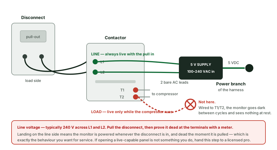
The supply takes 100–240 VAC and puts out 5 VDC. Its two bare AC leads land on the line side of the contactor — the same node as the load side of the disconnect. That way the monitor is powered whenever the disconnect is in, and dead the moment it is pulled.
Not on the load side. T1 and T2 are only live while the compressor runs. A monitor wired there goes dark between cycles and reports nothing at all about the system at rest — which is half of what it is for.
Dress the AC leads away from the contactor's moving parts, keep the low-voltage lead out of the panel where you can, and close the panel properly.
Plug in the splitter harness
Homeowner OK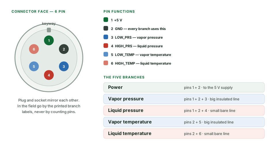
One plug goes into the monitor's splitter port. Five labelled branches come out, and each has exactly one place to go:
- Power → the power supply
- Vapor pressure → the sensor on the large insulated line
- Liquid pressure → the sensor on the small bare line
- Vapor temperature → the probe on the large insulated line
- Liquid temperature → the probe on the small bare line
Line up the keyway before you turn anything, push the connector fully home, then hand-tighten the collar. It should not need force in either direction. The pin map above is for diagnosis later — in the field, go by the printed labels.
Dress the cables
Homeowner OKThis is five minutes, and it is the difference between a product and a prototype.
- Every run secured. No cable touching the ground, no loops hanging off the cabinet face.
- Route the antenna lead along a cabinet edge, not across a panel.
- Leave a drip loop before each sensor so water runs off the cable rather than into it.
- Zip ties trimmed flush. No tails.
- Nothing routed across the coil face, the fan, or a service panel you will need to open again.
Restore power and read the lights
EveryonePush the disconnect back in. The left window lights immediately. The middle one starts blinking within a few seconds, and what it blinks tells you how far the unit has got.
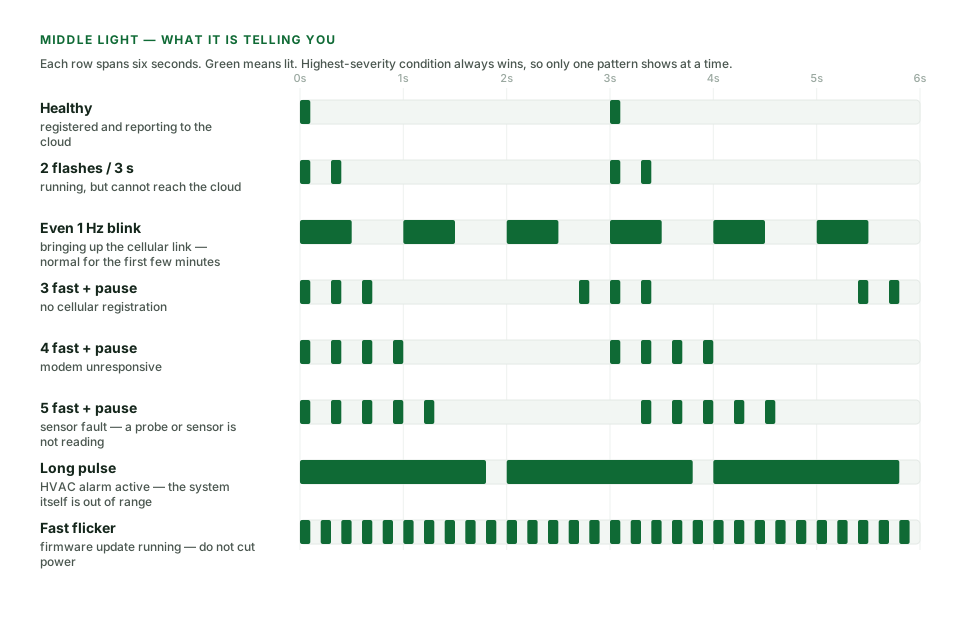
| Middle window | What it means | What to do |
|---|---|---|
| One flash every 3 s | Healthy — connected and reporting | Nothing. This is the one you are waiting for. |
| Even 1 Hz blink | Bringing up the cellular link | Normal for the first few minutes. Wait. |
| Two flashes, then a pause | On the network, but cannot reach the cloud | Usually clears itself. If it persists past ten minutes, call us. |
| Three fast, then a pause | No cellular registration after five minutes | Check the antenna is fitted and pointing up. Move the unit higher on the cabinet. |
| Four fast, then a pause | Modem unresponsive | Pull power for thirty seconds and restore it. If it repeats, the unit needs swapping. |
| Five fast, then a pause | Sensor fault — a probe or sensor is not reading | Re-seat every branch connector. Check the probe tip is on copper. |
| One long pulse | An HVAC alarm is active | The unit is fine; the system it is watching is out of range. Read the alert. |
| Fast flicker | Firmware updating | Do not cut power. It will finish on its own. |
Only one pattern shows at a time — the most serious condition always wins. A sensor fault outranks an alarm on purpose, because an alarm calculated from a faulty probe is not worth chasing.
Commission it before you walk away
EveryoneThis is the step that decides whether anybody has to come back. Do all of it standing at the condenser.
- Register the unit to the property — scan the QR code on the side label, or type the serial.
- Enter the equipment details you photographed in step 2.
- Run the system in cooling for ten minutes, then open the live view on your phone.
- Confirm all four channels are reading, and that the numbers are plausible — see below.
- Confirm the pressures are not the wrong way round. Liquid should read far higher than vapor.
- Send yourself a test alert and confirm it arrives.
If the unit is not reporting, do not leave. Diagnose it now. "We'll check on it remotely" turns into a second trip, and a second trip costs more than the first one earned.
Finish it properly
EveryoneClear the base of the unit, take the packaging away with you, wipe the enclosure face, and take the photographs listed further down this page. Then show the owner the live data on their own system — two minutes on that is worth more than anything written here.
What good readings look like
A sanity check, not a diagnosis. These are the figures you would expect from a healthy system running in cooling on a warm afternoon, roughly ten minutes into a cycle. If what you see is in a different world from this, something is wrong with the install or with the equipment — and either way you want to know before you leave.
| Channel | The general rule | R-410A at ~95 °F outdoor | R-22 at ~95 °F outdoor |
|---|---|---|---|
| Vapor pressure | Saturation around 35–50 °F | ~105–145 psi | ~60–85 psi |
| Liquid pressure | Saturation roughly 20–30 °F above outdoor air | ~340–420 psi | ~210–260 psi |
| Vapor line temp | Saturation plus 8–15 °F of superheat | ~50–65 °F | ~50–65 °F |
| Liquid line temp | Condensing temperature minus 8–12 °F of subcooling | ~95–115 °F | ~95–115 °F |
- Liquid pressure below vapor pressure means the sensors are swapped. Go back to step 6.
- Two pressures reading nearly the same on a system that has been off for hours is normal — the circuit has equalised. Run it and look again.
- A line temperature sitting at outdoor air temperature means the probe is not touching copper.
- A channel at its extreme — dead zero, or pinned at full scale — is a wiring or sensor fault, not a refrigerant fault.
Troubleshooting
| Symptom | Most likely cause | Fix |
|---|---|---|
| No lights at all | No power reaching the unit, or the harness power branch is not seated | Confirm the disconnect is in. Check the supply's AC leads at the contactor. Re-seat the power branch. |
| Powered, but nothing in the app | Still registering, or a weak signal where it is mounted | Give it ten minutes. Then move the unit higher on the cabinet, or onto a panel with a clearer view of the sky. |
| Three flashes that never clear | Poor cellular coverage at that spot | Reposition the antenna and the unit. Repeated power cycling will not fix a signal problem — send us the address and we will look at coverage. |
| Five flashes — sensor fault | A branch connector not fully home, or a probe not on copper | Unplug and re-seat all five branches. Re-tape the probe with the tip flat on the pipe. |
| One channel dead, the others fine | That sensor, or its lead | Swap that branch with its partner and see whether the fault follows the sensor or stays with the branch. That tells you which part to replace. |
| Pressures look inverted | Sensors on the wrong lines | Swap them on the pipes. Do not try to correct it in software. |
| Readings jump around | Cable strain at a connector, or a probe working loose | Add a drip loop and secure the cable. Re-tape the probe. |
Finishing standard
Every install ends the same way, whether it is your own house or the thirtieth one this month. It costs about five minutes and it is the cheapest quality control there is.
Before you leave
- Every wire secured; nothing touching the ground
- Antenna lead routed along an edge, not across a panel
- Unit level, beside the OEM labels rather than over them
- No field tape showing; insulation repaired neatly
- Base of the condenser clear — weeds, offcuts, packaging gone
- Enclosure face wiped clean
- Nothing leaning on the condenser or within 18 inches of the coil
Photographs to take
- The mounted unit, three-quarter angle
- Each pressure sensor on its tee
- Each temperature probe before you tape it
- The power connection inside the panel
- The equipment nameplate
- Your phone showing live data, held in front of the unit
Keep the photographs with the serial number. They are the warranty record, and they are the only thing that will tell you what was actually done here when somebody asks in three years.
Printable checklist
The short version, for the truck or the clipboard. Use the print button at the top of the page.
Install
- Power off at the disconnect, proved dead with a meter
- Both lines identified and marked
- Nameplate photographed
- Unit mounted level, clear of labels and airflow
- Antenna fitted, pointing up
- Tees fitted to both service ports
- Liquid sensor on the liquid line, vapor sensor on the vapor line
- All four refrigerant joints leak-checked
- Both probes taped, metal on copper, two patches each
- Power supply landed on the contactor line side
- All five harness branches seated, collars tightened
- Cables dressed, tied and trimmed
Commission
- Power restored; middle window at one flash every three seconds
- Unit registered to the property, serial recorded
- Equipment details entered
- All four channels reading live
- Readings plausible; pressures not inverted
- Test alert received on a phone
- Site left clean; photographs taken
- Owner shown their own live data
Stuck on something?
Call (940) 222-8333 or email sales@vetralis.com with the serial number from the side of the unit. If it is powered and talking to us, we can usually see what is wrong from here.